
LE-1218US RF
Amplifier is a 1.2 GHz bandwidth two-way amplifier.
It
provides excellent forward and reverse path
performance combined with high reliability and a user-friendly layout. GaAs
technology is used, that guarantees the excellent CTB and CSO performance. The device's USB
port communicates directly to the LE-1218US controller. It's easy to upgrade
the system and replace one component.
Features
l Supports 1.2 GHz bandwidth
l Up to 204 MHz with return
bandwidth
l Minimum needed of
installing and maintaining accessories such as pads and EQs
l Local monitoring, control
and set up via APP or 3 bit digital tube display and
adjust keypad
l On site changing frequency
split
l Switch the reverse path gain
adjust and Passive
l Compact design, small and
exquisite
l GaAs technology in use
l Improved ESD and Surge
protection
l Low noise figure
l One or two output can be determined by the
splitter position
Specifications
Table 1. Forward Path Specifications
|
Item |
Units |
Value |
|
Pass Band |
MHz |
85/105/258 - 1218 |
|
Gain1 |
dB |
42 |
|
Frequency Response |
dB |
± 0.75 |
|
Reference Output Level |
dBµV |
108 |
|
Input Attenuator Control Range |
dB |
0 - 20, 1 dB
step |
|
Input Equalizer Control Range |
dB |
0 - 20, 1 dB
step |
|
Input Cable Simulator |
dB |
0 - 10, 1 dB
step, Adjust via JXP PAD |
|
Interstage Attenuator Control Range |
dB |
0 - 20, 1 dB
step |
|
Interstage Equalizer Control Range |
dB |
0 - 20, 1 dB
step |
|
Return Loss |
dB |
16 |
|
RF Input Test Point |
dB |
- 20 ± 0.75 |
|
RF Output Test Point |
dB |
- 20 ± 0.75 |
|
Noise Figure1 |
dB |
7 |
|
Umax, 112 QAM Chs2 |
dBµV |
108 |
|
Output Level, CENELEC
42 Chs3 CTB: 60dBc3 CSO: 60dBc3 |
dBµV |
112 |
Notes:
1.
Forward Gain and Noise Figure measured with 10 dB
input EQ and 0 dB input pad.
2.
Maxima level, flat, CLC/TS 50083-3-3, N=24
3.
Distortion performance reference output level is 112
dBµV (1 port, Slope, 10dB @ 1200 MHz). Digital refers to 550 MHz to 1.2 GHz
loading with QAM carriers at -6 dB relative to analog CW carrier levels.
Table 2. Return Path Specifications
|
Item |
Units |
Value |
|
Pass Band |
MHz |
5 - 65/85/204 |
|
Gain |
dB |
25 |
|
Output Attenuator Control Range |
dB |
0 - 20, 1 dB
step |
|
Output Equalizer Control Range |
dB |
0 - 20, 1 dB
step |
|
Frequency Response |
dB |
± 0.75 |
|
Return Loss |
dB |
16 |
|
RF Test Point |
dB |
- 20 ± 0.1 |
|
Noise Figure |
dB |
6 |
|
Output Level |
dBµV |
110 |
Table 3. General Specifications
|
Item |
Units |
Value |
|
Power Consumption |
W |
18 |
|
Supply Voltage |
V AC |
26 - 65 or 110 - 264 |
|
RF Connectors |
- |
F-female, Imperial (Several Adapters Available) |
|
Test Point |
- |
F-female, Imperial (Internal) |
|
Dimensions ( W x H x D) |
mm |
236 x 145 x 90 |
|
Weight |
kg |
1.8 |
|
Water/Dust Ingress Protection
Rating |
- |
IP 65 |
|
Operating Temperature |
°C |
- 40 - + 55 |
|
Storage Temperature |
°C |
- 40 - + 80 |
|
Relative Humidity Range |
- |
5% - 95% |
Note: Unless otherwise noted, all specifications
reflect typical performance and are referenced to 20°C.
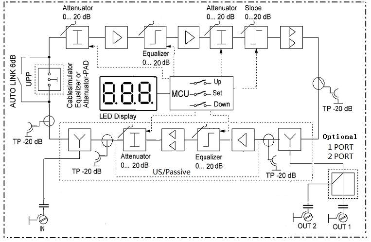
Block Diagram
Ordering information
|
Description |
Part
Number |
|
LE
- 1218US RF Amplifier, 1.2G, 65/85, 60V |
9920000024 |
|
LE
- 1218US RF Amplifier, 1.2G, 85/105, 60V |
9920000025 |
|
LE
- 1218US RF Amplifier, 1.2G, 204/258, 60V |
9920000026 |
|
LE
- 1218US RF Amplifier, 1.2G, 65/85, 230V,Europe Power cord |
9920000027 |
|
LE
- 1218US RF Amplifier, 1.2G, 85/105, 230V,Europe Power cord |
9920000028 |
|
LE
- 1218US RF Amplifier, 1.2G, 204/258, 230V,Europe Power cord |
9920000029 |


 苏公网安备32050902102581号